Sunday, June 5, 2016

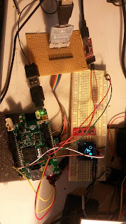
Progress on I/O processor for PI Zero/Orange PI

Made progress this week on I/O processor:

  1. PI zero CPU usage is down to 2% 
    1. Using DMA 64 byte packets 
    2. Sending two packets for one transaction 20us apart
      1. SPI rx/tx buffers are sent each clock, so, two transactions are needed., first transaction is CMD (Write/Read) elements the second is the response with the read data.  
  2. Updated I/O processor to use FreeRTOS v9.0.0.0
    1. Fixed interrupt priority issue causing lockup
    2. Adding I2C for LCD
    3. Need to test GPS serial 
    4. Adding PWM generation 
Here is a trace of a single transaction (CMD)/Response.  It takes .261ms to complete a CMD.  The I/O processor can process the command and re-trigger the DMA in less then 30us (Channel 04)


Sunday, May 29, 2016

PI zero vs GD32F103 DMA SPI Transfers

I would have never have guessed that a 106Mhz microcontroller can run circles around 1.xGhz ARM11 using SPI DMA transfers of 256 bytes.

So, what I'm I talking about?

  • GD32F103x is running at 106Mhz and using DMA for SPI and is configured as a slave.
  • PI Zero is a Master (maybe is using DMA transfers) SPI.  
  • SPI rate is 12Mhz (Close)
So, here is a logic analyzer trace:


Channel 4 is the GD32F103 raising the pin high at the top of the loop and lowering the pin after the DMA is configured waiting on the PI.

Using top to monitor CPU usage on the PI Zero:  spiExample, is taking 41% cpu usage (ouch).

Mem: 26956K used, 381340K free, 52K shrd, 1336K buff, 8332K cached
CPU:   0% usr  81% sys   0% nic  15% idle   0% io   0% irq   1% sirq
Load average: 1.41 0.80 0.61 1/97 247
  PID  PPID USER     STAT   VSZ %VSZ %CPU COMMAND
  244   202 root     R     3412   1%  41% ./spiExample
   71     2 root     SW       0   0%  10% [irq/56-dwc_otg]
   73     2 root     SW       0   0%   8% [irq/56-dwc_otg_]
  130     2 root     SW       0   0%   7% [spi0]
  127     2 root     SW       0   0%   6% [irq/44-DMA IRQ]
  128     2 root     SW       0   0%   5% [irq/45-DMA IRQ]
   72     2 root     SW       0   0%   5% [irq/56-dwc_otg_]
  247   202 root     R     2476   1%   1% top
    3     2 root     SW       0   0%   1% [ksoftirqd/0]
    4     2 root     SW       0   0%   0% [ktimersoftd/0]
   84     2 root     SW       0   0%   0% [irq/81-uart-pl0]
  133     1 root     S    20892   5%   0% /usr/sbin/vcfiled
  148     1 root     S     4144   1%   0% wpa_supplicant -B -i wlan0 -c /etc/wpa
  202     1 root     S     2476   1%   0% -sh
  203     1 root     S     2348   1%   0% /sbin/getty -L tty1 0 vt100
    1     0 root     S     2344   1%   0% init
   99     1 root     S     2344   1%   0% /sbin/syslogd -n
  101     1 root     S     2344   1%   0% /sbin/klogd -n
  201     1 root     S     2344   1%   0% udhcpc -i wlan0 -t 10 -b
  124     1 root     S     2208   1%   0% /usr/sbin/dropbear -R

Need to look into this:
  • Is the Pi Zero using interrupts for SPI (according to /proc/interrupts) no, it is only using DMA
  • Is it PREMPT_RT kernel? 
  • Doing some more testing it is setting a time between two back to back SPI packets.  But, it only lowers the CPU to 18% on the PI Zero.
    • The GDF32F103 only takes 62us to copy memory for slave and reload DMA buffers. 
Well, next is to connect GPS, PWM (oneshot and decode) on the GD32F103.

Review, the GD32F103 is a I/O processor handling the following:
  • PWM generation for the motors
  • PWM/PPM decode RC transmitter
  • I2C for LCD (Want to be able see status codes)
  • (1) LED on the GD32F103 board for general status. 
  • RS232 GPS
  • SPI slave device to the PI Zero 
    • The poll rate will be about 500hz
  • PI zero is running BaseFlight/HackFlight.   
Anyway,  so, this week will be processing GPS, 

Saturday, April 30, 2016

New quadcopter under development (Linux/Neo/OrangePI)


Finally have a new quadcopter design:

estimated cost: $215.00

If you notice, there is no Flight Controller; the last one was a Teensy 3.1 with BaseFlight; well this time it will be Linux as Flight Controller OS with micro-controller decoding PPM/PWM and generating the PWM out for the ESC.

Which board?  Udoo Neo will be the first one, the second board will be a Orange PI.  The goal is to use Linux with PREMPT enabled.  Did some initail testing with OrangePI with 4.6-rc4 and was able to generate a 50Hz square wave while running stress-ng, with no issues! 

Using the Neo first because has a A9/M4 the Orange PI will need an external micro-controller.  

So, how to port BaseFlight to Linux?  
  1. Basics
    1. I2C: will use /sys/class/i2c
    2. SPI: Not supported yet; will get into that little latter
    3. PWM: (M4 Neo, OrangePI micro-controller)
    4. PPM/PWM deocde: (M4, OrangePI micro-controller)
    5. Software/Framework
      1. Boost ASIO
        1. asio offers as async/event loop
          1. High performance timers
          2. Support for serial events
          3. Support for network events
          4. Add support for DIO interrupts
      2. Boost logging
        1. integrated
      3. BaseFlight
        1. has a single poll loop to process events
          1. Will move each of these events to asio event:
            1. Serial: for GPS / Baseflight configurator
            2. Timer: process loop for FC
            3. Network: External WIFI (NEW)

Why not use use Ardcopter or TauLabs?  This is a first pass and will be moving to one of them on the next round. Already have ported BaseFlight to Teensy 3.1; so already familiar with the code.

Which Kernel?  Right now, the Udoo Neo is 4.5 with some patches for RPMSG.  OrangePI, did some testing with 4.6-rc5; but waiting for more patches to go into mainline; so, 4.7.

BaseFlight has been ported to Linux; just debugging I2C; then pull apart main.c /loop and move to boost asio.  Will post the modifications in a few weeks.  Right now, getting Udoo Neo RPMSG working in 4.5.  

Thursday, April 21, 2016

Udoo Neo booting mainline v4.5

I've several projects going on with the Udoo Neo that required new version of the kernel; i.e adding several wifi adapters to create a router on different channels and mesh network.

Anyway, to get mainline working, need to move several of the udoo_neoo dt files and edit them.

Using mainline several issues arise:
- Support for HDMI driver; rpmsg, NTSC camera, etc.

For this project I just need rpmsg and NTSC camera.  So, over the next few weeks will be posting how and creating patch files using buildroot to create a bootable Linux image.

Sunday, February 21, 2016

TCP/IP over rpmsg OpenAMP with Udoo Neo

Finally got Ethernet driver for Linux completed using rpmsg and FreeRTOS LwIP working on the M4.  Curently the implementation is using Ethernet frames (includes destination/source MAC address and EtherType 14 bytes)  LwIP has iperf feature builtin for testing.  The MTU size is small (496-14)=482 bytes.  

Here is a code snippet:

static void
lwiperf_report(void *arg, enum lwiperf_report_type report_type,
  const ip_addr_t* local_addr, u16_t local_port, const ip_addr_t* remote_addr, u16_t remote_port,
  u32_t bytes_transferred, u32_t ms_duration, u32_t bandwidth_kbitpsec)
{
  LWIP_UNUSED_ARG(arg);
  LWIP_UNUSED_ARG(local_addr);
  LWIP_UNUSED_ARG(local_port);

  PRINTF("IPERF report: type=%d, remote: %s:%d, total bytes: %d, duration in ms: %d, kbits/s: %d\n",
    (int)report_type, ipaddr_ntoa(remote_addr), (int)remote_port, bytes_transferred, ms_duration, bandwidth_kbitpsec);
}


static void usrTask (void* param)
{
    struct rpmsg_endpoint *ept;
    int len;
    int result;

    vTaskSuspendAll();
    PRINTF("\r\n" VERSION " %s Task running... \r\n", __FUNCTION__);
    PRINTF("RPMSG Init as Remote\r\n");
    xTaskResumeAll ();

    result = rpmsg_rtos_init(0 /*REMOTE_CPU_ID*/, &rdev, RPMSG_MASTER, &app_chnl);
    assert(0 == result);
    vTaskSuspendAll();
    PRINTF("Name service handshake is done, M4 has setup a rpmsg channel [%d ---> %d]\r\n", app_chnl->src, app_chnl->dst);
    xTaskResumeAll ();
    
    
     lwipConfig();
     IP4_ADDR(&gw, 192,168,0,1);
     IP4_ADDR(&ipaddr, 192,168,0,2);
     IP4_ADDR(&netmask, 255,255,255,0);
     
    netif_add(&netif, &ipaddr, &netmask, &gw, NULL, rpmsg_init_drv, ethernet_input);
    PRINTF("INFO: %s %s %d \n",__FILE__,__FUNCTION__, __LINE__);

   netif_set_default(&netif);
   PRINTF("INFO: %s %s %d \n",__FILE__,__FUNCTION__, __LINE__);

   netif_set_up(&netif);
    PRINTF("INFO: %s %s %d \n",__FILE__,__FUNCTION__, __LINE__);

    ept = rpmsg_rtos_create_ept(app_chnl,USR_ENDPT);
    
    lwiperf_start_tcp_server_default(lwiperf_report, NULL);

running iperf:

# iperf -c 192.168.0.2
------------------------------------------------------------
Client connecting to 192.168.0.2, TCP port 5001
TCP window size: 23.8 KByte (default)
------------------------------------------------------------
[  3] local 192.168.0.1 port 50292 connected with 192.168.0.2 port 5001
[ ID] Interval       Transfer     Bandwidth
[  3]  0.0-10.4 sec   896 KBytes   707 Kbits/sec
# iperf -c 192.168.0.2
------------------------------------------------------------
Client connecting to 192.168.0.2, TCP port 5001
TCP window size: 23.8 KByte (default)
------------------------------------------------------------
[  3] local 192.168.0.1 port 50293 connected with 192.168.0.2 port 5001
[ ID] Interval       Transfer     Bandwidth
[  3]  0.0-10.4 sec   896 KBytes   709 Kbits/sec
# iperf -c 192.168.0.2
------------------------------------------------------------
Client connecting to 192.168.0.2, TCP port 5001
TCP window size: 23.8 KByte (default)
------------------------------------------------------------
[  3] local 192.168.0.1 port 50294 connected with 192.168.0.2 port 5001
[ ID] Interval       Transfer     Bandwidth
[  3]  0.0-10.3 sec   896 KBytes   711 Kbits/sec

from the M4:
IPERF report: type=1, remote: 192.168.0.1:50292, total bytes: 917528, duration in ms: 10613, kbits/s: 688                                                         
IPERF report: type=1, remote: 192.168.0.1:50292, total bytes: 917528, duration in ms: 10613, kbits/s: 688          
IPERF report: type=1, remote: 192.168.0.1:50294, total bytes: 917528, duration in ms: 10609, kbits/s: 688                                                         


Udoo Neo using I2C with Linux and Python

On my current quadcopter the LED on the Teensy 3.1 is used for ARM/DISAM indicator for the transmitter.  It is an important feature, allows me to know if the transmitter controls are active, i.e. any movement of the controls will turn on the propellers.

It would be nice to provide some more information, i.e battery information, compass calibration etc and keeping the weight down, found the following I2C LCD

Found several examples from Adafruit and several examples using micropython.  I updated the example to use python-smbus and it is working. The display is also part of the multiWii code base.


Thursday, February 11, 2016

TCP/IP working over rpmsg Udoo Neo

After fixing some issues with the Linux Ethernet driver icmp messages are working; ie. ping  Here is the output:

64 bytes from 192.168.0.2: seq=16 ttl=255 time=155.408 ms
[   75.265223] rpmsg_ether_xmit tx 98 enpt 125
[   75.407927] rpmsg_ethernet_dev_ept_cb rx 98
64 bytes from 192.168.0.2: seq=17 ttl=255 time=151.219 ms
[   76.270780] rpmsg_ether_xmit tx 98 enpt 125
[   76.412822] rpmsg_ethernet_dev_ept_cb rx 98
64 bytes from 192.168.0.2: seq=18 ttl=255 time=155.193 ms
[   77.275430] rpmsg_ether_xmit tx 98 enpt 125
[   77.417460] rpmsg_ethernet_dev_ept_cb rx 98
64 bytes from 192.168.0.2: seq=19 ttl=255 time=150.969 ms
[   78.280982] rpmsg_ether_xmit tx 98 enpt 125
[   78.422822] rpmsg_ethernet_dev_ept_cb rx 98
64 bytes from 192.168.0.2: seq=20 ttl=255 time=154.991 ms
[   79.285741] rpmsg_ether_xmit tx 98 enpt 125
[   79.426708] rpmsg_ethernet_dev_ept_cb rx 98
64 bytes from 192.168.0.2: seq=21 ttl=255 time=150.756 ms

Yes, it slow, but I have a lot of logging messages. Progress...