Saturday, November 12, 2016

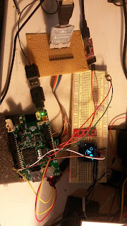
LinuxFlight parts list

Making progress:

  • Fixed gyro interrupt.
    • Able to single with gyro ISR callback using epoll, and GPIO.  Need to merge into the flight controller loop.
    • Started moving code for GPS parsing using C++/ boost ASIO
Here is the parts list:
Opted to use a OrangePI Zero over the Neo AIR.  The goal is to get something in the air and then move to using a camera OSD/OpenCV.

Still can use a USB camera for a simple test.  

Here is a trace of the flight controller loop at 8Khz.  What is interesting is the I2C poll for the baro/Mag.


Saturday, November 5, 2016

LinuxFlight Progress OrangePI PC

Testing barometer(MS5611) and compass (HMC5883L) with CleanFlight configurator.  The first trial will be with the OPC, then with the new OrangePI Zero.

Things to do:

  • Need to add GPIO interrupt callback to sync the gryo
  •  Merge GPS parser boost asio thread. 
  • Add blackbox logging
  • lttng logging to validate timing
Some progress, going to order quad-frame, moters,esc, etc.  Time it is all assembly board should be ready along with firmware. 

Any questions? 


Wednesday, October 26, 2016

OrangePI PC with Buildroot and Linux-4.9 (LinuxFlight)

The OrangePI PC booting/working with 4.9-rc1.  This is possible due to https://github.com/megous/linux/tree/orange-pi-4.9 github project.

[    0.000000] Linux version 4.9.0-rc1 (tcmichals@tcmichals-Studio-540) (gcc version 5.4.0 (Buildroot 2016.11-git-01024-g731b3c5) ) #6

So far have tested:

  • Ethernet works
  • I2C works.
  • THS works
  • Added some patches to SPI  Instead of using the entire patch, just changed the FIFO to 64 and added DT changes.  Also changed spidev.c and added:

static const struct of_device_id spidev_dt_ids[] = {
{ .compatible = "rohm,dh2228fv" },
{ .compatible = "lineartechnology,ltc2488" },
        { .compatible = "spidev" },  //TCM:FIX 

One issue just encountered several days ago is how to run Java; the solution is Java SE embedded.  Just follow the instructions here.

# java -version
java version "1.8.0_111"
Java(TM) SE Embedded Runtime Environment (build 1.8.0_111-b14, profile compact1, headless)
Java HotSpot(TM) Embedded Client VM (build 25.111-b14, mixed mode)

The goal of LinuxFlight is to be able to run Java, Python and C++ plugins/modules.  Pieces of the flight code can be offloaded to other modules, or to different programming languages. 

The current goal is to use Python to load and "wire" modules, with additional configuration.  This allows:
  • First module, will be GPS.  All of the parsing and configuration of the GPS will be written in python and calls into the Flight controller software.  Now, different GPS modules can be added using python. 

Saturday, October 15, 2016

LinuxFlight connecting to CleanFlight Configurator

Just finished updating github LinuxFlight.  CleanFlight Configurator, is not able to connect and start sending MSP packets; but something is hanging up in getting data messages.  Work on that next week.

How to build LinuxFlight (Linux only):
  • Need to build boost C++ libraries and install them 
  • make
  • ./PC
  • open another terminal 
    •  socat -d -d pty,raw,echo=0 tcp:localhost:56000
    • This will create a pty, the output from socat show which pty to connect configurator
      • i.e /dev/pts/9

There is a lot to do to improve the IPC speed, i.e not to copy std::vector, but to use std::move, so there is no copy.  Also, move the IPC queue struct from std::queue to boost::lockfree::queue with a semaphore to wake up the FC thread.  

The heart of the IPC is a send-reply via std::function<void (void)> type function.  So, how can a void function be able to process arguments and do process callbacks?  
  • Use std::bind, this arguments.   For example, in  mspSerialTCPPort.h,  function: handle_read creates a std::function<void (void)> 
                  msgPost_t _msg;
                  mspCallback_t _callback = std::bind(&mspSerialTCPClient::postHandleWrite,                                                                                            shared_from_this(),                                                                                                                                std::placeholders::_1);
                      _msg.m_in = std::bind(&callToMSPFromTCP, _pkt, _callback);

    So, msgPost_t is created with a function callback.  The std::bind takes the packet and places it in one of the arguments.  Along with a call back function.  It is important to use shared_ptr, so the class does not disappear until all callbacks are completed. So, when the function is invoked the arguments are unpacked and the MSP function is call.

    This is a simple way, to keep a callback IPC API and allow any type of arguments.  Yes, it is confusing, but look at the code, run it and debug it. 


    So, the current design is to move most of the I/O from the flight controller main thread, this way I2C. serial, etc are processed out side of the thread.  All data will be posted to the FC thread, this way, this should minimize jitter.  


    Saturday, October 8, 2016

    LinuxFlight github

    After several rounds of code porting and trying to keep the code compatible with a micro-controller decided to just move to Linux only port.

    The goal is to keep the main Flight-Controller loop reads accelerometer, and gyro, and move the reset of the I/O to read threads.  This way keeps the main loop on time.

    Also, the Neo Air is out, so, that will be the FC board with I/O processor.

    • ARM Linux board
      • GPS (Serial)
      • MS5611  (I2C)
      • MPU9250 (SPI)
      • I/O processor (USB)
      • MSP via TCP/IP
      • RX (Need to validate and test serial Ports are able to handle iBUS, or sBUS)
    • I/O processor
      • RX (PWM or Serial)
      • Telemetry
      • PWM out (motor control)
    So, go, but making progress.. 

    Saturday, September 24, 2016

    OrangePI PC with 4.8.x using buildroot

    Finally got some time to get back to testing OrangePI-PC as a Flight Controller board.  The OrangePI-PC offers several advantages over the Pi Zero:
    • Multiple serial ports (3) 
    • Multiple USB ports (each have port has its own controller not a Hub)
    • Camera (Still working on that)
    • Cost is low around $12

    I'm using standard buildroot with the orangePI defconfig, but using a different Linux kernel which has several patches for Ethernet, USB (slave), and thermal control (Which is big).   Using orange-pi-4.8 branch.

    Also made a couple of code changes:
    • spidev 
    static const struct of_device_id spidev_dt_ids[] = {
        { .compatible = "rohm,dh2228fv" },
        { .compatible = "lineartechnology,ltc2488" },
            { .compatible = "spidev" },

    • device tree: 
      • sun8i-h3-orangepi-pc.dts:
            spi0_pins_a: spi0@0 {
                    allwinner,pins = "PC0", "PC1", "PC2";
                    allwinner,function = "spi0";
                    allwinner,drive = <SUN4I_PINCTRL_10_MA>;
                    allwinner,pull = <SUN4I_PINCTRL_NO_PULL>;
                };

        spi0_cs0_pins_a: spi0_cs0@0 {
                    allwinner,pins = "PC3";
                    allwinner,function = "spi0";
                    allwinner,drive = <SUN4I_PINCTRL_10_MA>;
                    allwinner,pull = <SUN4I_PINCTRL_NO_PULL>;
                };
               
            i2c0_pins_a: i2c0@0 {
            allwinner,pins = "PA11", "PA12";
                allwinner,function = "i2c0";
                allwinner,drive = <SUN4I_PINCTRL_10_MA>;
                allwinner,pull = <SUN4I_PINCTRL_NO_PULL>;
            };

    .....
    &spi0 {
        pinctrl-names = "default";
        pinctrl-0 = <&spi0_pins_a>, <&spi0_cs0_pins_a>;
        status = "okay";
            spidev0: spidev@0 {
                    #address-cells = <1>;
                #size-cells = <0>;
                compatible = "spidev";
            reg = <0>;
            spi-max-frequency = <50000000>;
            };
    };

    &i2c0 {
        pinctrl-names = "default";
        pinctrl-0 = <&i2c0_pins_a>;
        status = "okay";
    }; 

        • sun8i-h3.dtsi
            spi0: spi@01c68000 {
                compatible = "allwinner,sun6i-a31-spi";
                reg = <0x01c68000 0x1000>;
                interrupts = <GIC_SPI 65 IRQ_TYPE_LEVEL_HIGH>;
                clocks = <&ccu CLK_BUS_SPI0>, <&ccu CLK_SPI0>;
                clock-names= "ahb", "mod";
                resets = <&ccu RST_BUS_SPI0>;
                dmas = <&dma 23>, <&dma 23>;
                dma-names = "rx", "tx";
                status = "disabled";
                #address-cells = <1>;
                #size-cells = <0>;
            };
           
            i2c0: i2c@01c2ac00 {
                compatible = "allwinner,sun6i-a31-i2c";
                reg = <0x01c2ac00 0x400>;
                interrupts = <GIC_SPI 6 IRQ_TYPE_LEVEL_HIGH>;
                clocks = <&ccu CLK_BUS_I2C0>;
                resets = <&ccu  RST_BUS_I2C0>;
                status = "disabled";
                #address-cells = <1>;
               
    #size-cells = <0>;
            };
    So, this adds a SPI interface and another I2C.

    Next is to do some testing with SPI and I2C.

    Also, still adding code to CleanFlight port to Linux.   Please post if you have any questions. 

    Sunday, September 11, 2016

    Cleanflight Fork

    Finally had time to create a github project for CleanFlight fork.  Over the next few weeks will post changes to allow CleanFlight to compile on Linux . 

    There are a couple targets:
    • PC - Allows CleanFlight to run on a PC and connect to a I/O processor
      • Helps in debugging and test with CleanFlight configurator
    • PI Zero
      • Connected a powered USB hub to the PI
        • Connected WIFI dongle
        • Connect I/O processor
    • Orange PI
      • Still working/waiting for some fixes to mainline, but will push forward with the basic camera.
    Right now, working on creating a I/O processor board.  This will be a simple perf board wired up by hand.  The reason for doing this, simple and cheap.  The following sensors will be supported
    • GPS
    • Compass
    • PWM In for RC
    • PWM out to motors
    •  USB

    The board for the PI Zero will also be a perf board.  But, it will use machine pin headers to keep the profile low.  This board will have just two sensors:

    Wednesday, August 24, 2016

    Cleanflight Confgurator

    Finally got CleanFlight Configurator communicating to PI Zero with CleanFlight.  Basic setup:

    1. Chrome With CleanFlight Configurator
      1. socat to create a pty to TCP socket
      2. socat -d -d pty,raw,echo=0 tcp:192.168.0.15:56000
        1. socat will display which port it created, i.e /dev/pty/20 then take this device and use it for the serial port "URL" in cleanflight.
    2. PI Zero
      1. CleanFlight Port
        1. TCP server to accept MSP messages
        2. Pipe the MSP messages into Cleanflight

    Gyro information was displayed in the Configurator, need to figure out why compass and accelerometer was not working. 

    Also, need to connect I/O processor to Cleanflight to forward RX info and GPS status.

    Friday, August 19, 2016

    I/O processor status

    Completed PWM input decode and sending results via USB.  For the first pass I'm using a HK-T6A transmitter/receiver.

    Overall Status:

    • I/O processor:  GD32F103 (red pill board) 
      • Interprocess commuinication via USB complete
        • Receiver PWM decode
        • GPS decode
      • Next is to do PWM for motor control
        • Standard PWM out
        • Support one shot125
        • Need validate USB jitter and performance
          • Out should be less then a 1ms
          • In should be no more then 2ms
    • Cleanflight
      • Update IPC using USB
      • Add socat for CleanFlight Configuration Web Tool
        •  open a TCP/IP port in CleanFlight 
        • use socat on Linux to forward MSP packets.


    Friday, July 15, 2016

    CleanFlight port to PI Zero

    Finally have MPU-9255 and MS5611 sensors working and a simple CLI on the command line.  It is simlar to CLI via serial port or CleanFlight configurator.

    Here is the output:
    linuxflight>tasks
    Task list          max/us  avg/us rate/hz maxload avgload     total/ms
     0 -       SYSTEM      29       0       9    0.5%    0.5%         0
     1 -     GYRO/PID     748     145     848   63.9%   12.7%       743
     3 -       SERIAL      71       1      93    1.1%    0.5%         1
     5 -           RX       0       0   2147483647    0.5%    0.5%         0
    linuxflight>tasks
    Task list          max/us  avg/us rate/hz maxload avgload     total/ms
     0 -       SYSTEM      31       0       9    0.5%    0.5%         1
     1 -     GYRO/PID     886     176     801   71.4%   14.5%      5864
     3 -       SERIAL      73       1      88    1.1%    0.5%         9
     5 -           RX       0       0   2147483647    0.5%    0.5%         0
    linuxflight>

    I'm going to switch to linenoise for controlling line processing to allow up and down errors etc. 

    Need to fix how average is calculated, but making progress.  Need to reconnect the I/O processor to get GPS, pwm out, s.bus in, and S.Port.

    The goal is to use socat where configurator is running to expose a virtual serial port and forward the packets to "LinuxFlight".

    Still working on CPU performance and getting GPIO to trigger for gyro-sync.

    Here is top:


    Here is the CLI on the PI Zero:


    The command line is using boost ASIO.  Goal is to add the socat protocol so configurator can still access and configure "LinuxFlight" ;)

    Yes, I'm thinking of forking the code, due to the amount of changes to the core.  Right now, there are very minimal.


    Sunday, July 10, 2016

    Progress PI Zero Flight controller

    I have BetaFlight ported to the PI Zero, but opted to move to CleanFlight due to the latest code check-in.  There are several APIs that are abstracted to make porting to Linux easier. The basic idea is to use LINUX #define to comment out micro-controller specific code and add XXX_linux.c drivers for SPI, I2C, serial, pwm, etc.   Still going to stick with boost ASIO for scheduler, still based on timers (timerfd). 

    The SPI communication to the GD32F1 is progressing:
    • GPS handling, moved baud rate, GPS update rate to GD32F1
    • Simplifies command/processing and speed
    • Working on PWM decoding (PPM/PWM)
    • Working PWM encoding 4 outputs

    Have SPI working with MPU-9255 at 8Mhz from the PI Zero.  

    Still pending:
    • Cannot find any more "red" GD32F103 board might have to move to another board
    • Transmitter
      • Turnigry 9xr pro?
      • Radiolink at 10
        • The main difference between the two are:
          • Telemetry s.bus vs i2C 
          • Have to buy another receiver Radiolink to have s.bus and i2c telemetry (R9DS) which is another $13.
          • Radiolink is not open source but many ports and docs on decoding i2c for telemetry. 
          • Radiolink has sliders 9xr pro does not
          • HK shipping costs and pricing changes. 
          • Thoughts?

    Sunday, June 5, 2016

    Progress on I/O processor for PI Zero/Orange PI

    Made progress this week on I/O processor:

    1. PI zero CPU usage is down to 2% 
      1. Using DMA 64 byte packets 
      2. Sending two packets for one transaction 20us apart
        1. SPI rx/tx buffers are sent each clock, so, two transactions are needed., first transaction is CMD (Write/Read) elements the second is the response with the read data.  
    2. Updated I/O processor to use FreeRTOS v9.0.0.0
      1. Fixed interrupt priority issue causing lockup
      2. Adding I2C for LCD
      3. Need to test GPS serial 
      4. Adding PWM generation 
    Here is a trace of a single transaction (CMD)/Response.  It takes .261ms to complete a CMD.  The I/O processor can process the command and re-trigger the DMA in less then 30us (Channel 04)


    Sunday, May 29, 2016

    PI zero vs GD32F103 DMA SPI Transfers

    I would have never have guessed that a 106Mhz microcontroller can run circles around 1.xGhz ARM11 using SPI DMA transfers of 256 bytes.

    So, what I'm I talking about?

    • GD32F103x is running at 106Mhz and using DMA for SPI and is configured as a slave.
    • PI Zero is a Master (maybe is using DMA transfers) SPI.  
    • SPI rate is 12Mhz (Close)
    So, here is a logic analyzer trace:


    Channel 4 is the GD32F103 raising the pin high at the top of the loop and lowering the pin after the DMA is configured waiting on the PI.

    Using top to monitor CPU usage on the PI Zero:  spiExample, is taking 41% cpu usage (ouch).

    Mem: 26956K used, 381340K free, 52K shrd, 1336K buff, 8332K cached
    CPU:   0% usr  81% sys   0% nic  15% idle   0% io   0% irq   1% sirq
    Load average: 1.41 0.80 0.61 1/97 247
      PID  PPID USER     STAT   VSZ %VSZ %CPU COMMAND
      244   202 root     R     3412   1%  41% ./spiExample
       71     2 root     SW       0   0%  10% [irq/56-dwc_otg]
       73     2 root     SW       0   0%   8% [irq/56-dwc_otg_]
      130     2 root     SW       0   0%   7% [spi0]
      127     2 root     SW       0   0%   6% [irq/44-DMA IRQ]
      128     2 root     SW       0   0%   5% [irq/45-DMA IRQ]
       72     2 root     SW       0   0%   5% [irq/56-dwc_otg_]
      247   202 root     R     2476   1%   1% top
        3     2 root     SW       0   0%   1% [ksoftirqd/0]
        4     2 root     SW       0   0%   0% [ktimersoftd/0]
       84     2 root     SW       0   0%   0% [irq/81-uart-pl0]
      133     1 root     S    20892   5%   0% /usr/sbin/vcfiled
      148     1 root     S     4144   1%   0% wpa_supplicant -B -i wlan0 -c /etc/wpa
      202     1 root     S     2476   1%   0% -sh
      203     1 root     S     2348   1%   0% /sbin/getty -L tty1 0 vt100
        1     0 root     S     2344   1%   0% init
       99     1 root     S     2344   1%   0% /sbin/syslogd -n
      101     1 root     S     2344   1%   0% /sbin/klogd -n
      201     1 root     S     2344   1%   0% udhcpc -i wlan0 -t 10 -b
      124     1 root     S     2208   1%   0% /usr/sbin/dropbear -R

    Need to look into this:
    • Is the Pi Zero using interrupts for SPI (according to /proc/interrupts) no, it is only using DMA
    • Is it PREMPT_RT kernel? 
    • Doing some more testing it is setting a time between two back to back SPI packets.  But, it only lowers the CPU to 18% on the PI Zero.
      • The GDF32F103 only takes 62us to copy memory for slave and reload DMA buffers. 
    Well, next is to connect GPS, PWM (oneshot and decode) on the GD32F103.

    Review, the GD32F103 is a I/O processor handling the following:
    • PWM generation for the motors
    • PWM/PPM decode RC transmitter
    • I2C for LCD (Want to be able see status codes)
    • (1) LED on the GD32F103 board for general status. 
    • RS232 GPS
    • SPI slave device to the PI Zero 
      • The poll rate will be about 500hz
    • PI zero is running BaseFlight/HackFlight.   
    Anyway,  so, this week will be processing GPS, 

    Saturday, April 30, 2016

    New quadcopter under development (Linux/Neo/OrangePI)


    Finally have a new quadcopter design:

    estimated cost: $215.00

    If you notice, there is no Flight Controller; the last one was a Teensy 3.1 with BaseFlight; well this time it will be Linux as Flight Controller OS with micro-controller decoding PPM/PWM and generating the PWM out for the ESC.

    Which board?  Udoo Neo will be the first one, the second board will be a Orange PI.  The goal is to use Linux with PREMPT enabled.  Did some initail testing with OrangePI with 4.6-rc4 and was able to generate a 50Hz square wave while running stress-ng, with no issues! 

    Using the Neo first because has a A9/M4 the Orange PI will need an external micro-controller.  

    So, how to port BaseFlight to Linux?  
    1. Basics
      1. I2C: will use /sys/class/i2c
      2. SPI: Not supported yet; will get into that little latter
      3. PWM: (M4 Neo, OrangePI micro-controller)
      4. PPM/PWM deocde: (M4, OrangePI micro-controller)
      5. Software/Framework
        1. Boost ASIO
          1. asio offers as async/event loop
            1. High performance timers
            2. Support for serial events
            3. Support for network events
            4. Add support for DIO interrupts
        2. Boost logging
          1. integrated
        3. BaseFlight
          1. has a single poll loop to process events
            1. Will move each of these events to asio event:
              1. Serial: for GPS / Baseflight configurator
              2. Timer: process loop for FC
              3. Network: External WIFI (NEW)

    Why not use use Ardcopter or TauLabs?  This is a first pass and will be moving to one of them on the next round. Already have ported BaseFlight to Teensy 3.1; so already familiar with the code.

    Which Kernel?  Right now, the Udoo Neo is 4.5 with some patches for RPMSG.  OrangePI, did some testing with 4.6-rc5; but waiting for more patches to go into mainline; so, 4.7.

    BaseFlight has been ported to Linux; just debugging I2C; then pull apart main.c /loop and move to boost asio.  Will post the modifications in a few weeks.  Right now, getting Udoo Neo RPMSG working in 4.5.  

    Thursday, April 21, 2016

    Udoo Neo booting mainline v4.5

    I've several projects going on with the Udoo Neo that required new version of the kernel; i.e adding several wifi adapters to create a router on different channels and mesh network.

    Anyway, to get mainline working, need to move several of the udoo_neoo dt files and edit them.

    Using mainline several issues arise:
    - Support for HDMI driver; rpmsg, NTSC camera, etc.

    For this project I just need rpmsg and NTSC camera.  So, over the next few weeks will be posting how and creating patch files using buildroot to create a bootable Linux image.

    Sunday, February 21, 2016

    TCP/IP over rpmsg OpenAMP with Udoo Neo

    Finally got Ethernet driver for Linux completed using rpmsg and FreeRTOS LwIP working on the M4.  Curently the implementation is using Ethernet frames (includes destination/source MAC address and EtherType 14 bytes)  LwIP has iperf feature builtin for testing.  The MTU size is small (496-14)=482 bytes.  

    Here is a code snippet:

    static void
    lwiperf_report(void *arg, enum lwiperf_report_type report_type,
      const ip_addr_t* local_addr, u16_t local_port, const ip_addr_t* remote_addr, u16_t remote_port,
      u32_t bytes_transferred, u32_t ms_duration, u32_t bandwidth_kbitpsec)
    {
      LWIP_UNUSED_ARG(arg);
      LWIP_UNUSED_ARG(local_addr);
      LWIP_UNUSED_ARG(local_port);

      PRINTF("IPERF report: type=%d, remote: %s:%d, total bytes: %d, duration in ms: %d, kbits/s: %d\n",
        (int)report_type, ipaddr_ntoa(remote_addr), (int)remote_port, bytes_transferred, ms_duration, bandwidth_kbitpsec);
    }


    static void usrTask (void* param)
    {
        struct rpmsg_endpoint *ept;
        int len;
        int result;

        vTaskSuspendAll();
        PRINTF("\r\n" VERSION " %s Task running... \r\n", __FUNCTION__);
        PRINTF("RPMSG Init as Remote\r\n");
        xTaskResumeAll ();

        result = rpmsg_rtos_init(0 /*REMOTE_CPU_ID*/, &rdev, RPMSG_MASTER, &app_chnl);
        assert(0 == result);
        vTaskSuspendAll();
        PRINTF("Name service handshake is done, M4 has setup a rpmsg channel [%d ---> %d]\r\n", app_chnl->src, app_chnl->dst);
        xTaskResumeAll ();
        
        
         lwipConfig();
         IP4_ADDR(&gw, 192,168,0,1);
         IP4_ADDR(&ipaddr, 192,168,0,2);
         IP4_ADDR(&netmask, 255,255,255,0);
         
        netif_add(&netif, &ipaddr, &netmask, &gw, NULL, rpmsg_init_drv, ethernet_input);
        PRINTF("INFO: %s %s %d \n",__FILE__,__FUNCTION__, __LINE__);

       netif_set_default(&netif);
       PRINTF("INFO: %s %s %d \n",__FILE__,__FUNCTION__, __LINE__);

       netif_set_up(&netif);
        PRINTF("INFO: %s %s %d \n",__FILE__,__FUNCTION__, __LINE__);

        ept = rpmsg_rtos_create_ept(app_chnl,USR_ENDPT);
        
        lwiperf_start_tcp_server_default(lwiperf_report, NULL);

    running iperf:

    # iperf -c 192.168.0.2
    ------------------------------------------------------------
    Client connecting to 192.168.0.2, TCP port 5001
    TCP window size: 23.8 KByte (default)
    ------------------------------------------------------------
    [  3] local 192.168.0.1 port 50292 connected with 192.168.0.2 port 5001
    [ ID] Interval       Transfer     Bandwidth
    [  3]  0.0-10.4 sec   896 KBytes   707 Kbits/sec
    # iperf -c 192.168.0.2
    ------------------------------------------------------------
    Client connecting to 192.168.0.2, TCP port 5001
    TCP window size: 23.8 KByte (default)
    ------------------------------------------------------------
    [  3] local 192.168.0.1 port 50293 connected with 192.168.0.2 port 5001
    [ ID] Interval       Transfer     Bandwidth
    [  3]  0.0-10.4 sec   896 KBytes   709 Kbits/sec
    # iperf -c 192.168.0.2
    ------------------------------------------------------------
    Client connecting to 192.168.0.2, TCP port 5001
    TCP window size: 23.8 KByte (default)
    ------------------------------------------------------------
    [  3] local 192.168.0.1 port 50294 connected with 192.168.0.2 port 5001
    [ ID] Interval       Transfer     Bandwidth
    [  3]  0.0-10.3 sec   896 KBytes   711 Kbits/sec

    from the M4:
    IPERF report: type=1, remote: 192.168.0.1:50292, total bytes: 917528, duration in ms: 10613, kbits/s: 688                                                         
    IPERF report: type=1, remote: 192.168.0.1:50292, total bytes: 917528, duration in ms: 10613, kbits/s: 688          
    IPERF report: type=1, remote: 192.168.0.1:50294, total bytes: 917528, duration in ms: 10609, kbits/s: 688                                                         


    Udoo Neo using I2C with Linux and Python

    On my current quadcopter the LED on the Teensy 3.1 is used for ARM/DISAM indicator for the transmitter.  It is an important feature, allows me to know if the transmitter controls are active, i.e. any movement of the controls will turn on the propellers.

    It would be nice to provide some more information, i.e battery information, compass calibration etc and keeping the weight down, found the following I2C LCD

    Found several examples from Adafruit and several examples using micropython.  I updated the example to use python-smbus and it is working. The display is also part of the multiWii code base.


    Thursday, February 11, 2016

    TCP/IP working over rpmsg Udoo Neo

    After fixing some issues with the Linux Ethernet driver icmp messages are working; ie. ping  Here is the output:

    64 bytes from 192.168.0.2: seq=16 ttl=255 time=155.408 ms
    [   75.265223] rpmsg_ether_xmit tx 98 enpt 125
    [   75.407927] rpmsg_ethernet_dev_ept_cb rx 98
    64 bytes from 192.168.0.2: seq=17 ttl=255 time=151.219 ms
    [   76.270780] rpmsg_ether_xmit tx 98 enpt 125
    [   76.412822] rpmsg_ethernet_dev_ept_cb rx 98
    64 bytes from 192.168.0.2: seq=18 ttl=255 time=155.193 ms
    [   77.275430] rpmsg_ether_xmit tx 98 enpt 125
    [   77.417460] rpmsg_ethernet_dev_ept_cb rx 98
    64 bytes from 192.168.0.2: seq=19 ttl=255 time=150.969 ms
    [   78.280982] rpmsg_ether_xmit tx 98 enpt 125
    [   78.422822] rpmsg_ethernet_dev_ept_cb rx 98
    64 bytes from 192.168.0.2: seq=20 ttl=255 time=154.991 ms
    [   79.285741] rpmsg_ether_xmit tx 98 enpt 125
    [   79.426708] rpmsg_ethernet_dev_ept_cb rx 98
    64 bytes from 192.168.0.2: seq=21 ttl=255 time=150.756 ms

    Yes, it slow, but I have a lot of logging messages. Progress... 

    Saturday, January 30, 2016

    Updated MQX 4.1.0 with rpmsg

    Open-Amp and MQX 4.1.0

    The latest release from NXP is a port of the FreeRTOS operating system to the imx6sx SOC and imx7 SOC.  This release has rpmsg/open-amp along with drives and examples.  Also, here is a good overview of open-amp located here.  MQX uses MCC; until now, spend a few days last week porting rpmsg delivered by NXP to MQX 4.1.0.  FreeRTOS example is portable to MQX.    The main difference in porting open-amp to MQX, is the ISR only posts the channel message to a queue instead of calling open-amp stack and processing the message in the ISR. There are still some open issues; but it is working.

    At this time I don't know if it is possible to release the code due to all of the licensing issues; still need to see if it is possible;


    Saturday, January 23, 2016

    How to reload the same firmware on the Neo M4 without a reboot

    Reloading M4 without rebooting on the UDOO Neo


    Most of the time I have to modify and reload firmware on the M4 many times during a debug session, i.e adding debug code or features etc, and each time when reloading firmware the Neo must reboot each time.  This gets old; plus all of the time wasted.

    So, what is causes the firmware not to be reloaded? Well that is simple, it is the memory protection setup on the RDC, one simple way to to reload firmware to turn off the RDC protection, another way, just add a compile option and not enable RDC memory protection.

    For MQX, it is in the init_hardware.c file, function void rdc_init_memory(void) so, I added a simple #ifdef and allows the code to be reloaded.

    void RDC_memory_init(void)
    {
        uint32_t start, end;
    #if defined(__CC_ARM)
        extern uint32_t Image$$VECTOR_ROM$$Base[];
        extern uint32_t Image$$ER_m_text$$Limit[];
        extern uint32_t Image$$RW_m_data$$Base[];
        extern uint32_t Image$$RW_m_data$$Limit[];

        start = (uint32_t)Image$$VECTOR_ROM$$Base & 0xFFFFF000;
        end = (uint32_t)(Image$$ER_m_text$$Limit + (Image$$RW_m_data$$Limit - Image$$RW_m_data$$Base));
        end = (end + 0xFFF) & 0xFFFFF000;
    #else
        extern uint32_t __FLASH_START[];
        extern uint32_t __FLASH_END[];

        start = (uint32_t)__FLASH_START & 0xFFFFF000;
        end   = ((uint32_t)__FLASH_END + 0xFFF) & 0xFFFFF000;
    #endif
    #if _DEBUG_
    #pragma message "Turned off memory protection"
    #else
        RDC_SetMrAccess(RDC, rdcMrMmdc, start, end, (3 << (BOARD_DOMAIN_ID * 2)), true, false);    
    #endif
    }


    When compiling just define _DEBUG_ and  load the app.


    Sunday, January 17, 2016

    Udoo Neo M4 memory layout and performance

    The M4 has several non-contiguous memory blocks for code and data

    • TCM (tightly coupled memory)
      • TCMU
        • This is 32K SRAM for Code
      • TCML
        • This is 32K SRAM for Data
    • OCRAM
      • (Need to look into how much can be access TBD)
    • DDR
      • Linux sets aside 8MB 
        • A9 and M4 must share this RAM 
      • The last 1MB is used for MCC/RPMSG
    • SPI Flash

    The application baseflight port will be more then 32K of text (code)  So, the code must be in one memory or split.  

    Using a split method requires some up front work with the linker file and the loader.  It is possible to create a linker file putting some code in TCMU and DDR.  The idea being RTOS, interrupt; code which has a high bandwidth rate.  Less bandwidth code would go into DDR, or even OCRAM or SPI flash.

    Here is an example of a loader file:


    /* Specify the memory areas */
    MEMORY
    {
      m_interrupts          (RX)  : ORIGIN = 0x9ff00000, LENGTH = 0x00008000
      m_text                (RX)  : ORIGIN = 0x84000000, LENGTH = 0x00040000
      m_data                (RW)  : ORIGIN = 0x84040000, LENGTH = 0x00028000
    }

    __FLASH_START = ORIGIN(m_interrupts);
    __FLASH_END   = ORIGIN(m_text) + LENGTH(m_text);

    /* Define output sections */
    SECTIONS
    {
      /* The startup code goes first into Flash */
      .interrupts :
      {
        __VECTOR_TABLE = .;
        . = ALIGN(4);
        KEEP(*(.isr_vector))     /* Startup code */
        . = ALIGN(4);
        *croutine.c.obj (.text .text*)
        *event_groups.c.obj (.text .text*)
        *list.c.obj (.text .text*)
        *queue.c.obj (.text .text*)
        *tasks.c.obj (.text .text*)
        *timers.c.obj (.text .text*)
        *port.c.obj (.text .text*)
        *startup_MCIMX6X_M4.S.obj (.text .text*)
        *system_MCIMX6X_M4.c.obj (.text .text*)
        *uart_imx.c.obj (.text .text*)
        *mu_imx.c.obj (.text .text*)
        *heap_2.c.obj (.text .text*)
        *rpmsg_rtos.c.obj (.text .text*)
        *platform.c.obj (.text .text*)
        *hil.c.obj (.text .text*)
        *sh_mem.c.obj (.text .text*)
        *remote_device.c.obj (.text .text*)
        *rpmsg.c.obj (.text .text*)
        *rpmsg_ext.c.obj (.text .text*)
        *rpmsg_core.c.obj (.text .text*)
        *rpmsg_porting.c.obj (.text .text*)
        
        *baseflight.c.obj (.text .text*)
        
      } > m_interrupts

      /* The program code and other data goes into Flash */
      .text :
      {
        . = ALIGN(4);
        *(.text)                 /* .text sections (code) */
        *(.text*)                /* .text* sections (code) */
        *(.rodata)               /* .rodata sections (constants, strings, etc.) */
        *(.rodata*)              /* .rodata* sections (constants, strings, etc.) */
        *(.glue_7)               /* glue arm to thumb code */
        *(.glue_7t)              /* glue thumb to arm code */
        *(.eh_frame)
        KEEP (*(.init))
        KEEP (*(.fini))
        . = ALIGN(4);
      } > m_text


    The m_interrupt section, need to call out the file name with the text, this will move the code into the section.  So, for slow code put in DDR. 

    When creating a binary file, the code is it two separate sections:

      m_interrupts          (RX)  : ORIGIN = 0x9ff00000, LENGTH = 0x00008000
      m_text                (RX)  : ORIGIN = 0x84000000, LENGTH = 0x00040000

    so, the binary will span from 0x84000000 to 0x9FF08000.  So, to fix this, must use a Intel Hex file. The Intel hex file will only create records for the sections that need to be fixed with data.

    So, a M4 loader now must able to load intel hex files into memory.

    Also, the next pass will move .data sections into SRAM along with the stack. 


    Sunday, January 3, 2016

    UDOO Neo and openocd working

    With the help of IIRC openocd able to create a configuration file for openocd to connect to the M4 DAP and able to halt and reset just the M4 processor.

    I'm using an old Amontec JTAGkey (using FTDI 232 chip) here is a photos of the wiring.


    Using the imx6sx.cfg file and the following command to connect to M4.

    sudo  ./src/openocd -f interface/ftdi/jtagkey.cfg -f ./tcl/target/imx6sx.cfg

    Output:

    Open On-Chip Debugger 0.10.0-dev-00023-g8590315 (2016-01-02-19:34)
    Licensed under GNU GPL v2
    For bug reports, read
    http://openocd.org/doc/doxygen/bugs.html
    adapter speed: 1000 kHz
    Warn : imx6sx.sdma: nonstandard IR value
    Warn : imx6sx.sjc: nonstandard IR value
    imx6sx.dapM4
    Info : clock speed 1000 kHz
    Info : JTAG tap: imx6sx.dapM4 tap/device found: 0x4ba00477 (mfg: 0x23b, part: 0xba00, ver: 0x4)
    Info : JTAG tap: imx6sx.dapA9 tap/device found: 0x4ba00477 (mfg: 0x23b, part: 0xba00, ver: 0x4)
    Info : TAP imx6sx.sdma does not have IDCODE
    Info : JTAG tap: imx6sx.sjc tap/device found: 0x0891c01d (mfg: 0x00e, part: 0x891c, ver: 0x0)
    Info : imx6sx.dapM4: hardware has 6 breakpoints, 4 watchpoints


    Then start a gdb session:
    ./arm-none-eabi-gdb

    (gdb) tar ext :3333   <---- connects to openocd
    Remote debugging using :3333
    (gdb)  monitor  halt    <------------- halts only M4
    (gdb)  monitor  reset   <------------ reset M4 (resets the M4 and restarts from 0x0)

    Next will rebuild and see if M4 will single step...